1. Introduction
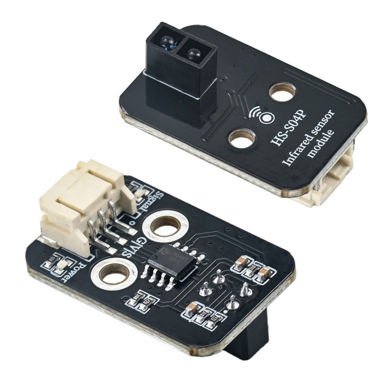
The infrared transmitter and receiver of the tracking sensor are greatly interfered by the ambient light, generally speaking, the closer to the reflective surface, the better the effect.Operating voltage: 3.3~5V.Check the reaction distance: 1-20mm.
2. Schematic
Tracking sensor-HS-S04B schematicClick to view
Module Parameters
Pin Name | description |
|---|---|
G | GND (Negative Power Input) |
V | VCC (Positive Power Input) |
S | Digital Signal Pin |
Power Supply Voltage: 3.3V / 5V
Connection Type: 2.54mm Header
Installation Method: Double Screw Fixed
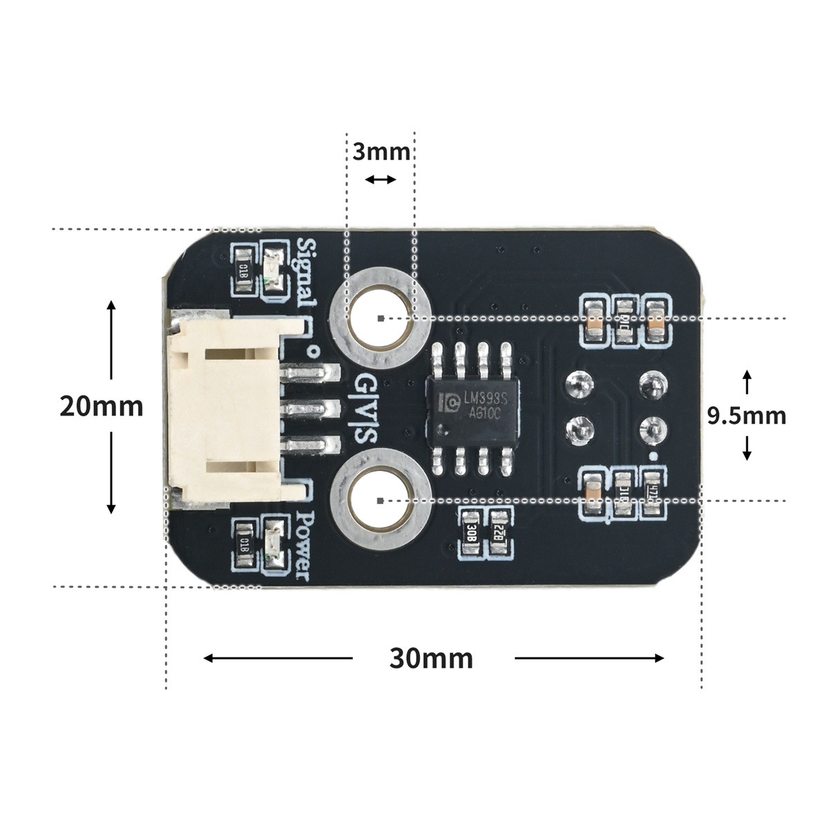
4, Circuit Board Size
5 of Arduino IDE example program
Attention: If prompted with an error message about the library file during program upload, please import the library file first!
Arduino IDE Library Download and Import Tutorial:Click to view
Example program (UNO development board):
void setup(){
  Serial.begin(9600);
  pinMode(2, INPUT);
  pinMode(13, OUTPUT);
}

void loop(){
  if (digitalRead(2) == 0) {
    Serial.println("bai se");
    digitalWrite(13,HIGH);

  } else {
    Serial.println("hei se");
    digitalWrite(13,LOW);

  }

}
6, Miciqi Mixly Example Program (Graphical Language)
Example program (UNO development board):Click to download
Attention: If prompted with an error message about the library file during program upload, please import the library file first!
Download and import tutorial of Mixly IDE Arduino library:Click to view
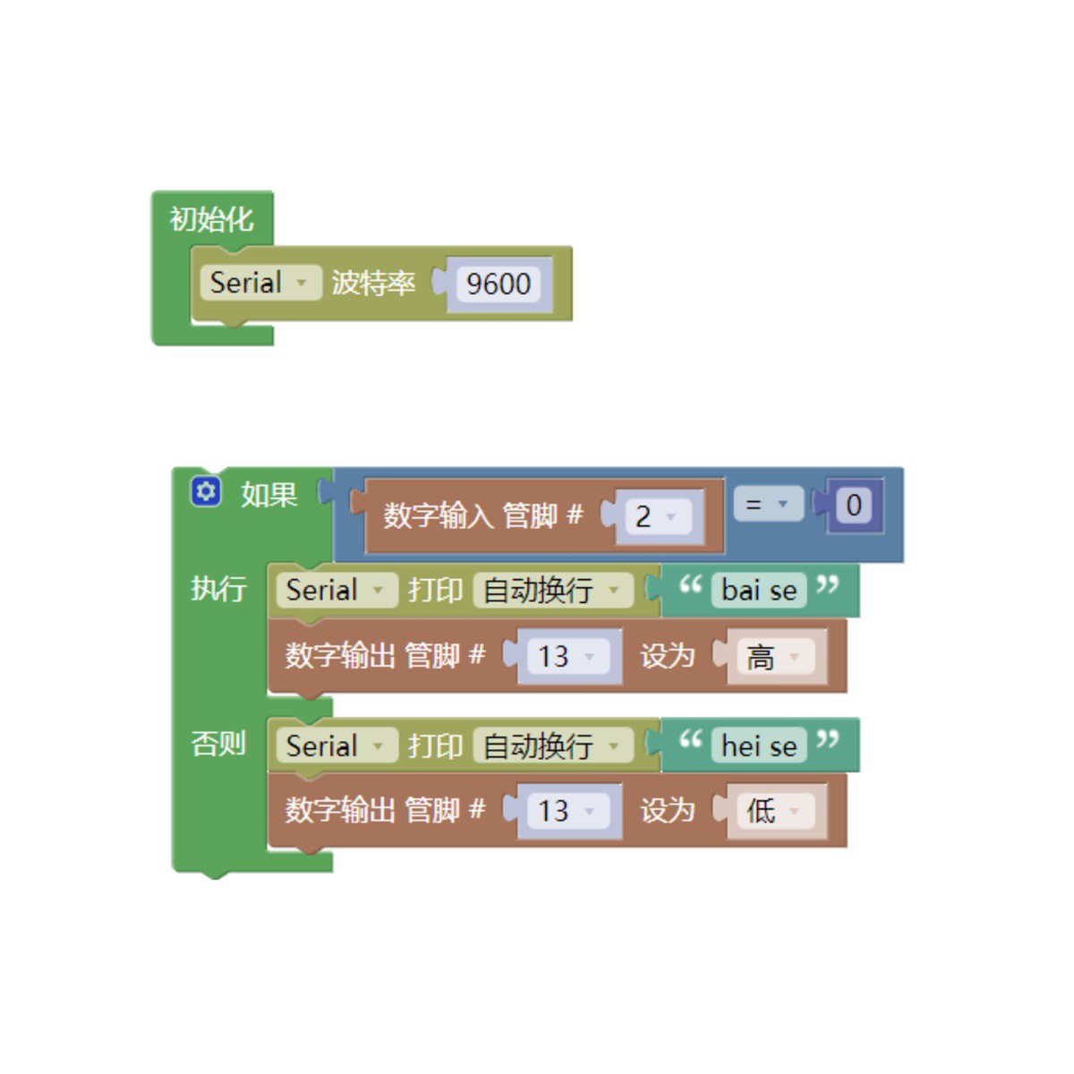
Example Program (ESP32 Development Board):
Pending update...
7, Test Environment Setup
Arduino UNO Test Environment Setup
Prepare Components:
HELLO STEM UNO R3 DEVELOPMENT BOARD *1
HELLO STEM UNO R3 P EXPANSION BOARD *1
USB TYPE-C DATA CABLE *1
Tracking Sensor (HS-S04B) *1
LED module (HS-F08P) *1
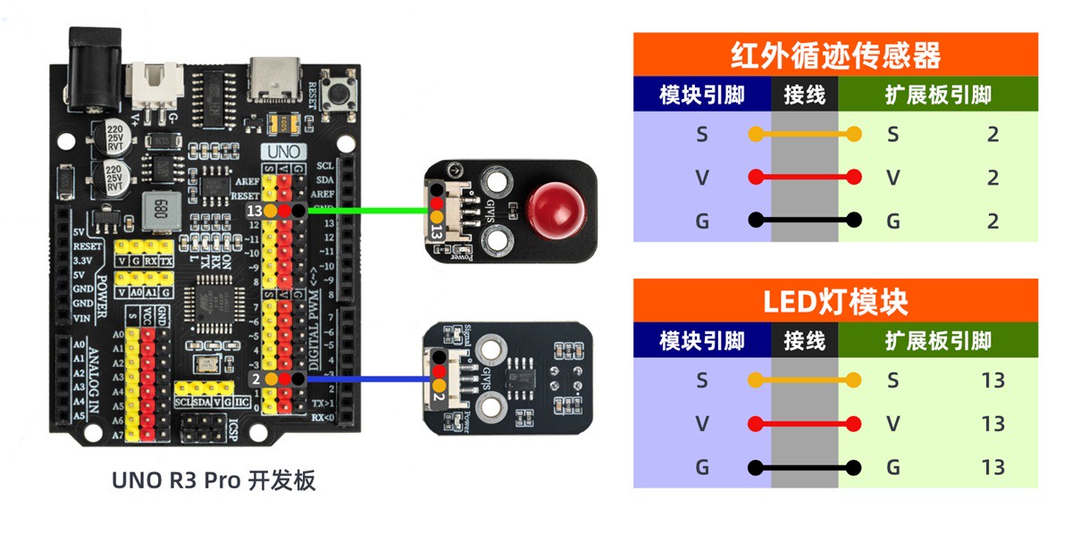
1P female to female DuPont wire *3 pieces or 3P female to female DuPont wire *1 piece
Circuit wiring diagram:
ESP32 Test Environment Setup
Prepare Components:Pending update...
Circuit wiring diagram:Pending update...
8. Test results
Arduino UNO test results:
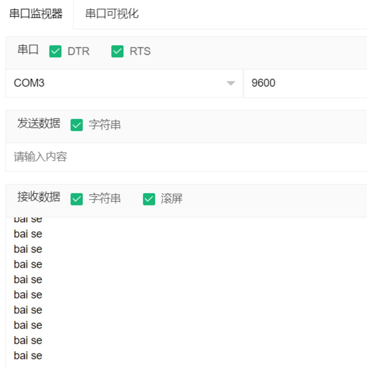
Trace sensor uses the working characteristics of infrared, infrared light is reflected when it encounters a white background, the receiver receives the reflected light, and after being shaped by an inverter (Schmitt trigger), it outputs a low level (0); the serial port prints "bai se", when infrared light encounters a black line, it is absorbed, and the receiver does not receive the reflected light, after being shaped by the inverter (Schmitt trigger), it outputs a high level (1), and the serial port prints "hei se".