
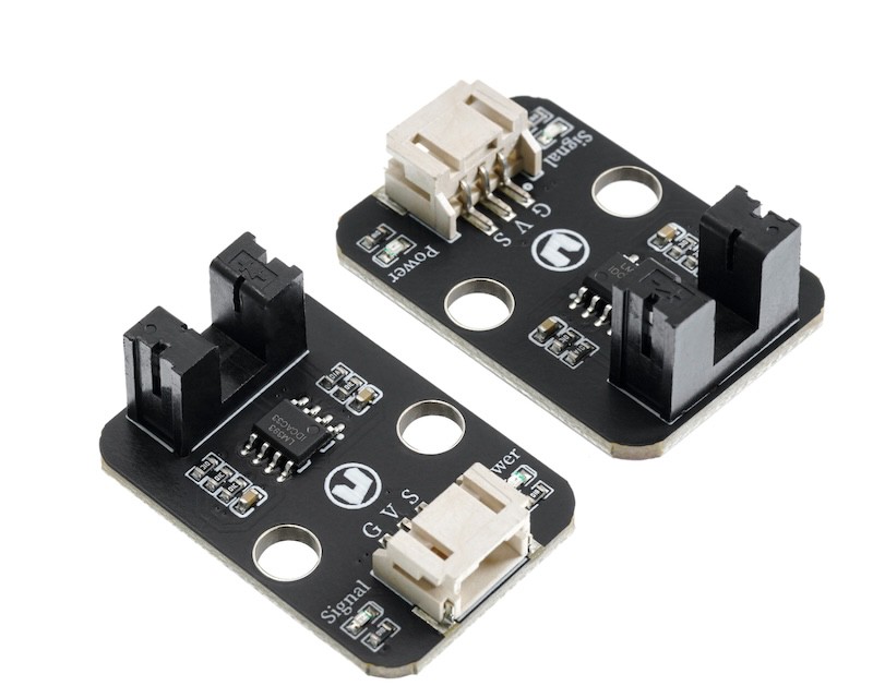
1. Introduction
2. Schematic
Slot type photoelectric sensor-HS-S59-L Schematic diagramClick to view
Module Parameters
Pin Name | description |
|---|---|
G | GND (Negative Power Input) |
V | VCC (Positive Power Input) |
S | Digital Signal Pin |
Power Supply Voltage: 3.3V / 5V
Connection method: PH2.0 3P terminal
Installation method: Screw fixed / Lego construction
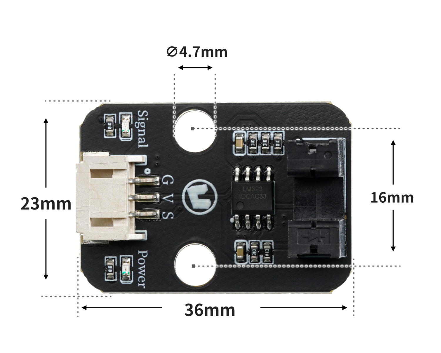
4, Circuit Board Size
5 of Arduino IDE example program
Attention: If prompted with an error message about the library file during program upload, please import the library file first!
Arduino IDE Library Download and Import Tutorial:Click to view
Example program (UNO development board):
void setup(){
  Serial.begin(9600);
  pinMode(3, INPUT);
  pinMode(10, OUTPUT);
}

void loop(){
  if (digitalRead(3) == 0) {
    Serial.println("有物体经过,点亮led");
    digitalWrite(10,HIGH);

  } else if (digitalRead(3) == 1) {
    Serial.println("未检测到物体,熄灭led");
    digitalWrite(10,LOW);
  }

}
6, ESP32 Python Example (for Mixly IDE/Misashi)
Choose the development board Python ESP32 [ESP32 Generic(4MB)] and upload in code mode
Attention: If prompted with an error message about the library file during program upload, please import the library file first!
Download and import tutorial for Mixly IDE ESP32 library:Click to view
Example program (ESP32-Python):
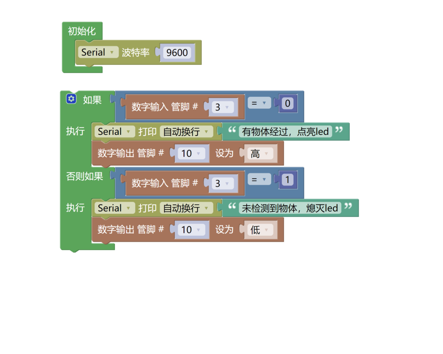
待更新...7, Mixly example program (graphical language)
Example program (UNO development board):Click to download
Attention: If prompted with an error message about the library file during program upload, please import the library file first!
Download and import tutorial of Mixly IDE Arduino library:Click to view
Example Program (ESP32 Development Board):Click to download
Attention: If prompted with an error message about the library file during program upload, please import the library file first!
Download and import tutorial for Mixly IDE ESP32 library:Click to view
Image pending update...
8. Setting up the Test Environment
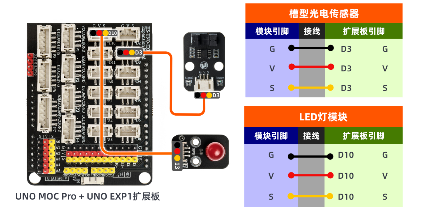
Arduino UNO Test Environment Setup
Prepare Components:
HELLO STEM UNO R3 DEVELOPMENT BOARD *1
HELLO STEM UNO R3 P EXPANSION BOARD *1
USB TYPE-C DATA CABLE *1
Slot type photoelectric sensor module (HS-S59-L) *1
LED lamp module (HS-F08-L) *1
PH2.0 3P dual-head terminal line *2
Circuit wiring diagram:
ESP32 Test Environment Setup
Prepare Components:Pending update...
Circuit wiring diagram:Pending update...
9, Video tutorial
Arduino UNO video tutorial:Click to view
ESP32 Python Video Tutorial:Click to view
10, Test results
Arduino UNO Test Conclusion:
After the device is connected to the wire, burn the above program to the UNO-R3PRO development board and then connect the power supply.Open the serial port monitor. When the slot photoelectric sensor detects an object passing by, turn on the LED. If no object is detected, turn off the LED.
ESP32 Python test conclusion:
Pending update...