1. Introduction
2. Schematic
3P Push Button Module - HS-KEY3-L SchematicClick to view
Module Parameters
Pin Name | description |
|---|---|
G | GND (Negative Power Input) |
V | VCC (Positive Power Input) |
1 | Digital Signal Pin |
2 | Digital Signal Pin |
3 | Digital Signal Pin |
Power Supply Voltage: 3.3V / 5V
Connection method: PH2.0 terminal wire
Installation method: Modular fixed
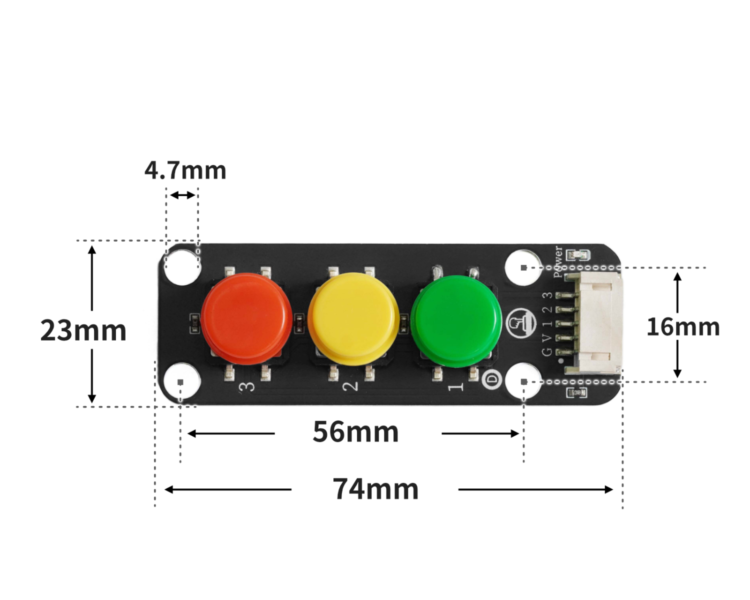
4, Circuit Board Size
5 of Arduino IDE example program
Attention: If prompted with an error message about the library file during program upload, please import the library file first!
Arduino IDE Library Download and Import Tutorial:Click to view
Example program (UNO development board):
volatile int light;

void setup(){
  light = 0;
  pinMode(6, OUTPUT);
  analogWrite(6, 0);
  pinMode(11, INPUT);
  pinMode(9, INPUT);
  pinMode(13, INPUT);
}

void loop(){
  //led灯接D6引脚:四位按键模块1~4分别接开发板11,9,13
  //
  //

  if (digitalRead(11) == 0) {
    light = 0;

  } else if (digitalRead(9) == 0) {
    light = 20;
  } else if (digitalRead(13) == 0) {
    light = 255;
  }
  delay(10);
  analogWrite(6, light);

}
6, ESP32 Python Example (for Mixly IDE/Misashi)
Choose the development board Python ESP32 [ESP32 Generic(4MB)] and upload in code mode
Attention: If prompted with an error message about the library file during program upload, please import the library file first!
Download and import tutorial for Mixly IDE ESP32 library:Click to view
Example program (ESP32-Python):
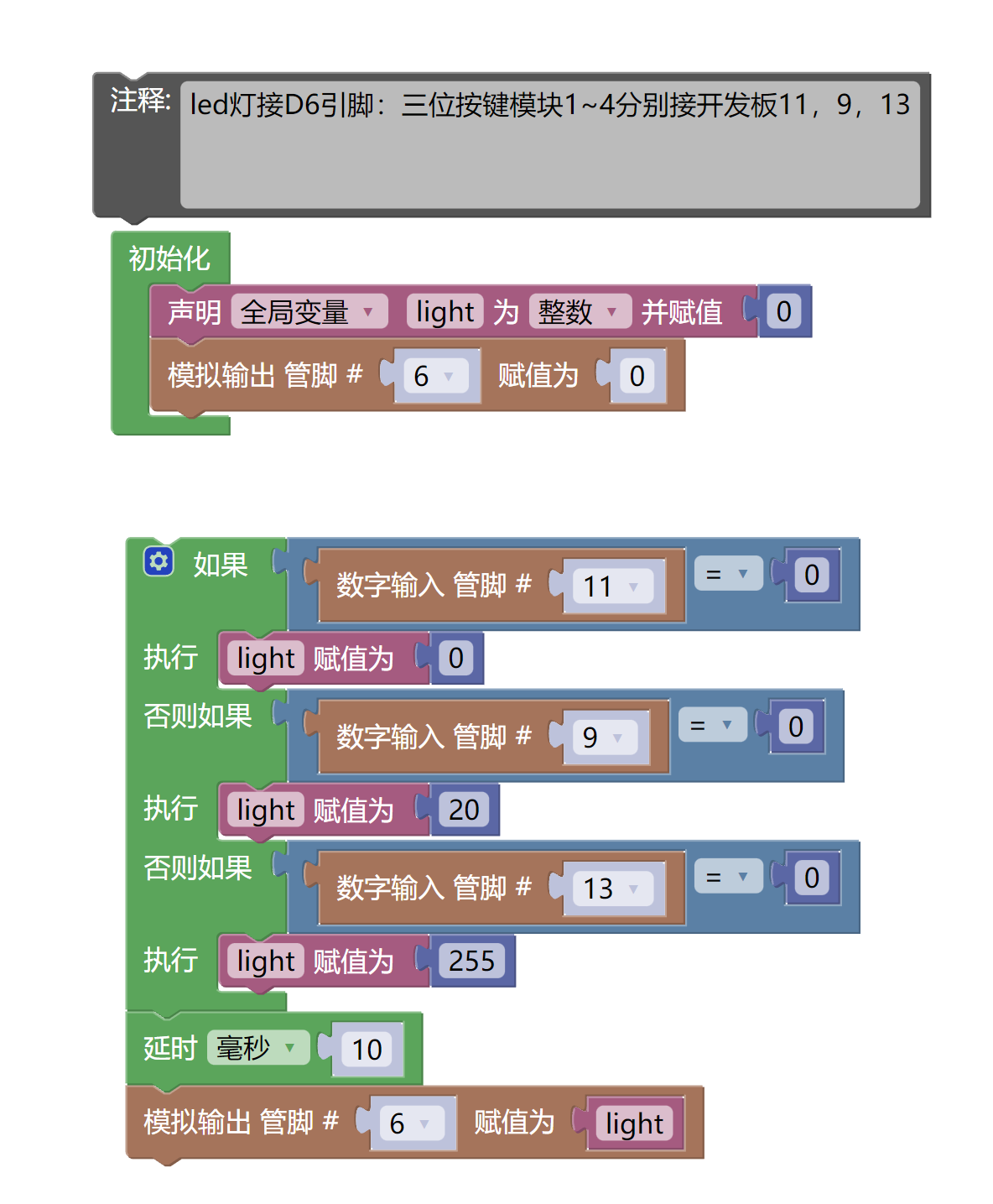
待更新...7, Mixly example program (graphical language)
Example program (UNO development board):Click to download
Attention: If prompted with an error message about the library file during program upload, please import the library file first!
Download and import tutorial of Mixly IDE Arduino library:Click to view
Example Program (ESP32 Development Board):Click to download
Attention: If prompted with an error message about the library file during program upload, please import the library file first!
Download and import tutorial for Mixly IDE ESP32 library:Click to view
Image pending update...
8. Setting up the Test Environment
Arduino UNO Test Environment Setup
Prepare Components:
HELLO STEM UNO R3 DEVELOPMENT BOARD *1
HELLO STEM UNO R3 P EXPANSION BOARD *1
USB TYPE-C DATA CABLE *1
LED module (HS-F08L) *1
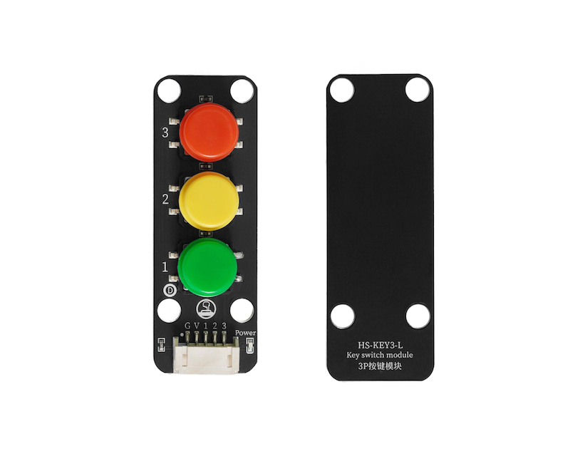
3-Simulated Pushbutton Module (HS-KEY3-L) *1
PH2.0 5P double-ended terminal line *1
PH2.0 3P dual headed terminal line *1
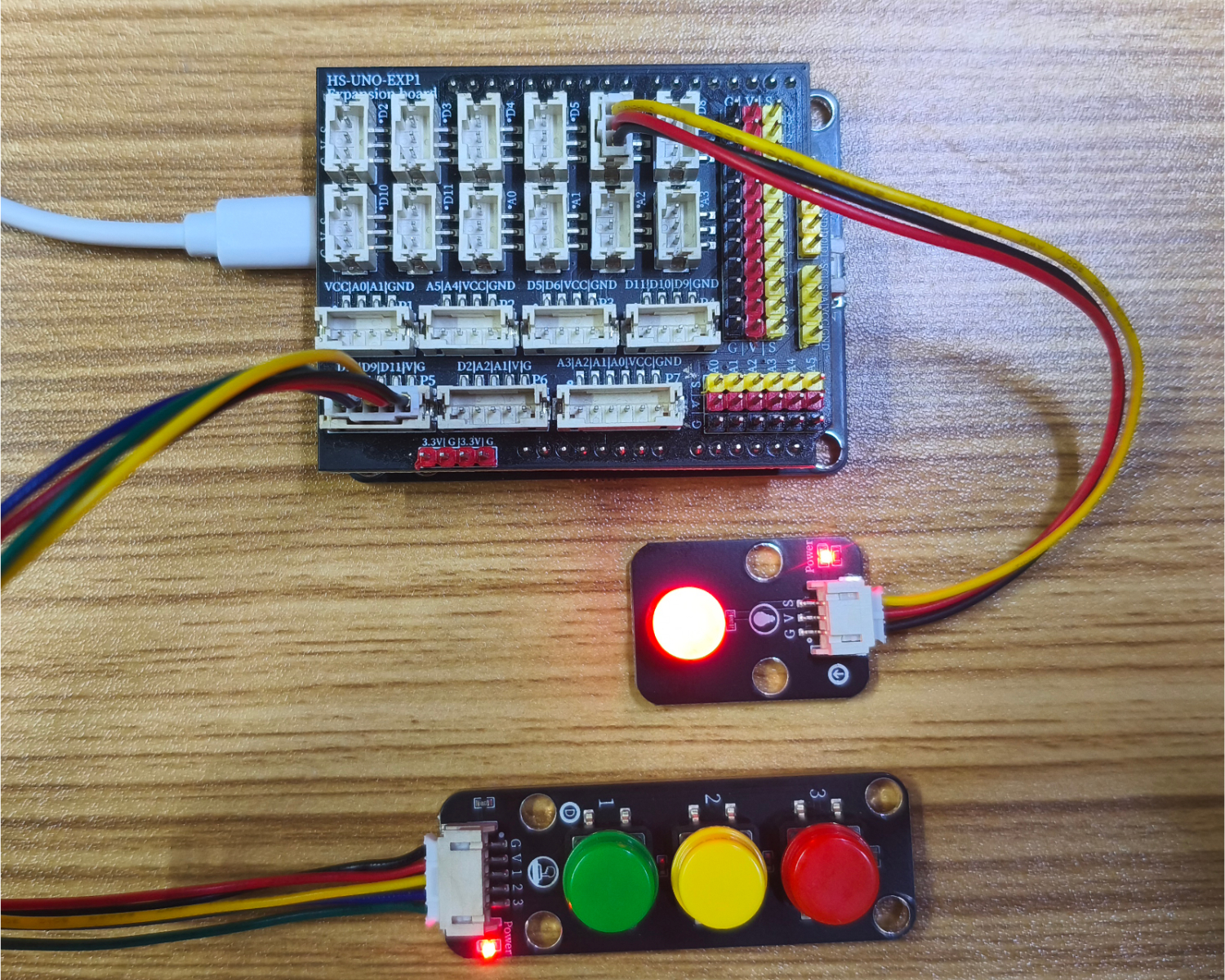
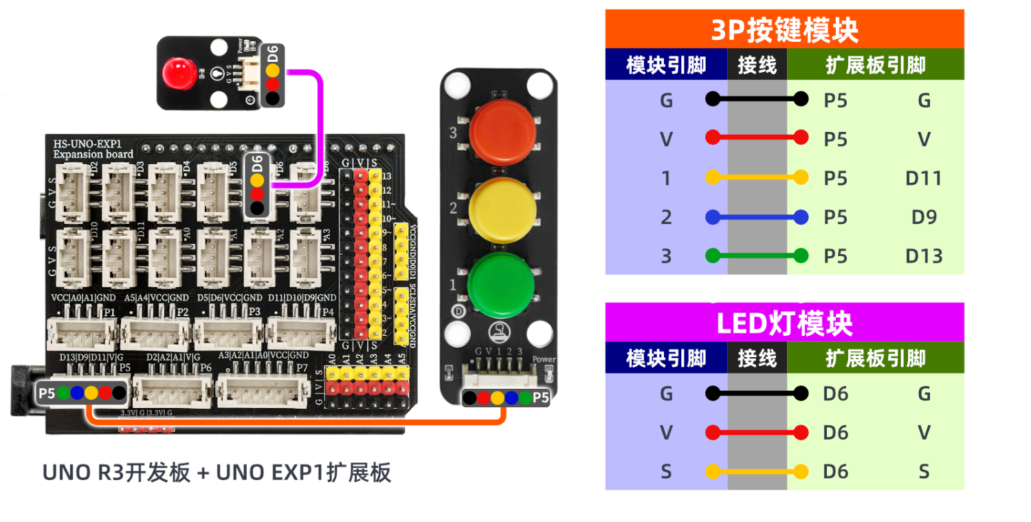
Circuit wiring diagram:
ESP32 Test Environment Setup
Prepare Components:Pending update...
Circuit wiring diagram:Pending update...
9, Video tutorial
Video tutorial: Click to view
10, Test results
Arduino UNO test results:
After the device is connected to the wire, burn the above program to the UNO-R3 PRO development board and then connect the power supply. Pressing different buttons will also change the brightness of the LED.