1. Introduction
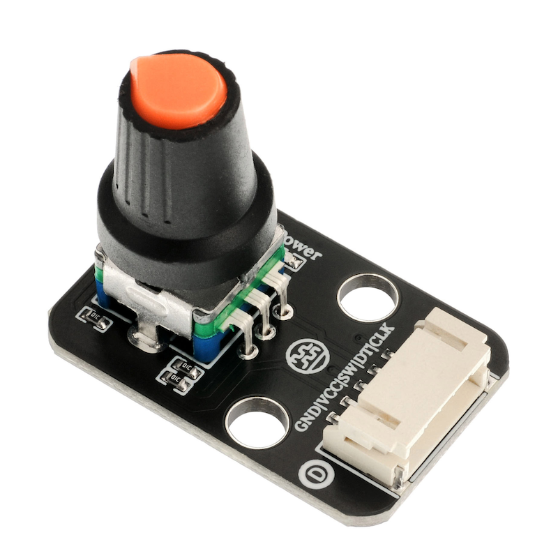
An encoder is a rotating type of sensor that converts rotational displacement into a series of digital pulse signals. By rotating, it can count the number of pulses output during the rotation process in both the positive and negative directions. The rotation count is unlike potentiometers, as this rotation count is unlimited.Cooperate with the buttons on the rotary encoder to enable certain specific functions.The reading system usually adopts a differential method, that is, two waveforms with the same shape but a phase difference of 180° are compared to improve the quality and stability of the output signal.Encoders are widely used in applications such as car volume and air conditioning adjustment.
2. Schematic
Encoder-HS-S32-L SchematicClick to view
Module Parameters
Pin Name | description |
|---|---|
G | GND (Negative Power Input) |
V | VCC (Positive Power Input) |
SW | Switch Pin |
DT | Data pin |
CLK | clock pin |
Power Supply Voltage: 3.3V / 5V
Connection method: PH2.0 terminal wire
Installation Method: Double Screw Fixed
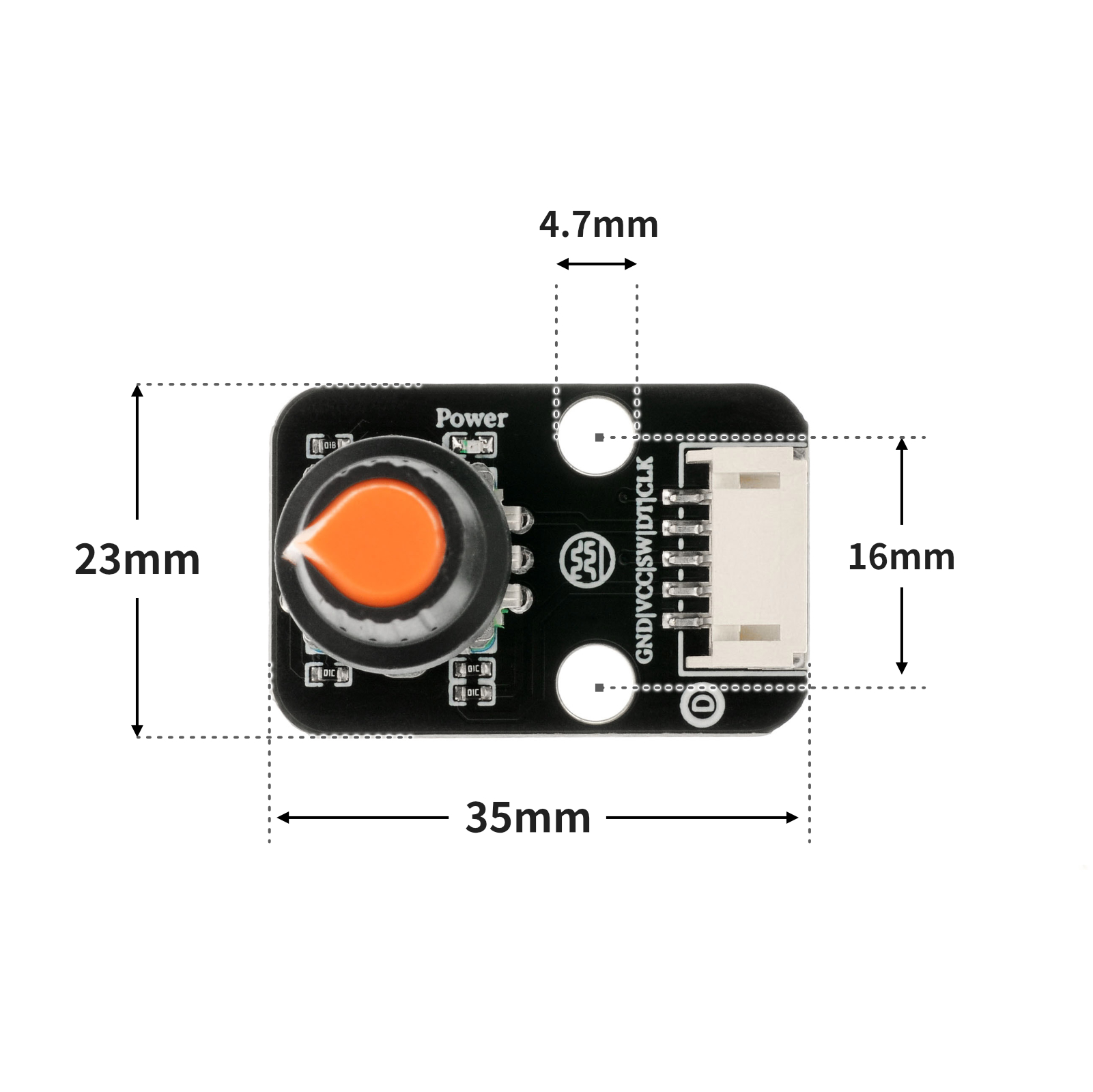
4, Circuit Board Size
5 of Arduino IDE example program
Attention: If prompted with an error message about the library file during program upload, please import the library file first!
Arduino IDE Library Download and Import Tutorial:Click to view
Example program (UNO development board):
volatile int lastCLK;
volatile int count;
void attachInterrupt_fun_RISING_2() {
procedure();
}
void procedure() {
int clkstate = digitalRead(2);
int dtstate = digitalRead(A2);
if (lastCLK != clkstate) {
lastCLK = clkstate;
}
count = count + ((clkstate != dtstate)?1:(-1));
Serial.println(count);
}
void setup(){
lastCLK = 0;
count = 0;
Serial.begin(9600);
pinMode(2, INPUT);
attachInterrupt(digitalPinToInterrupt(2),attachInterrupt_fun_RISING_2,RISING);
pinMode(A1, OUTPUT);
digitalWrite(A1,HIGH);
pinMode(A2, INPUT);
}
void loop(){
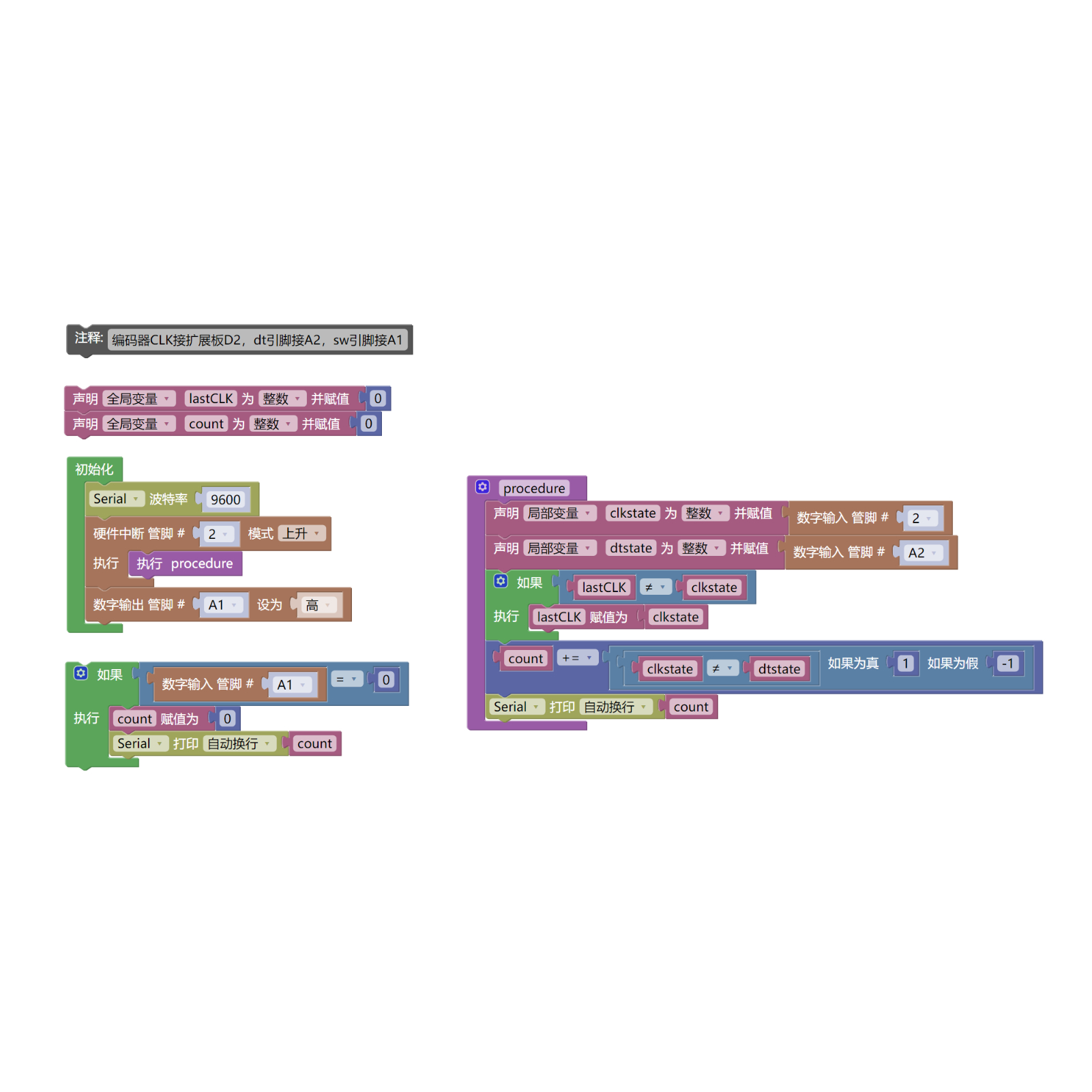
//编码器CLK接扩展板D2,dt引脚接A2,sw引脚接A1
if (digitalRead(A1) == 0) {
count = 0;
Serial.println(count);
}
}6, Miciqi Mixly Example Program (Graphical Language)
Example program (UNO development board):Click to download
Attention: If prompted with an error message about the library file during program upload, please import the library file first!
Download and import tutorial of Mixly IDE Arduino library:Click to view
7, Test Environment Setup
Arduino UNO Test Environment Setup
Prepare Components:
HELLO STEM UNO R3 DEVELOPMENT BOARD *1
HELLO STEM UNO R3 P EXPANSION BOARD *1
USB TYPE-C DATA CABLE *1
Rotating Encoder Module (HS-S32L) *1
PH2.0 5P Dupont wire *1
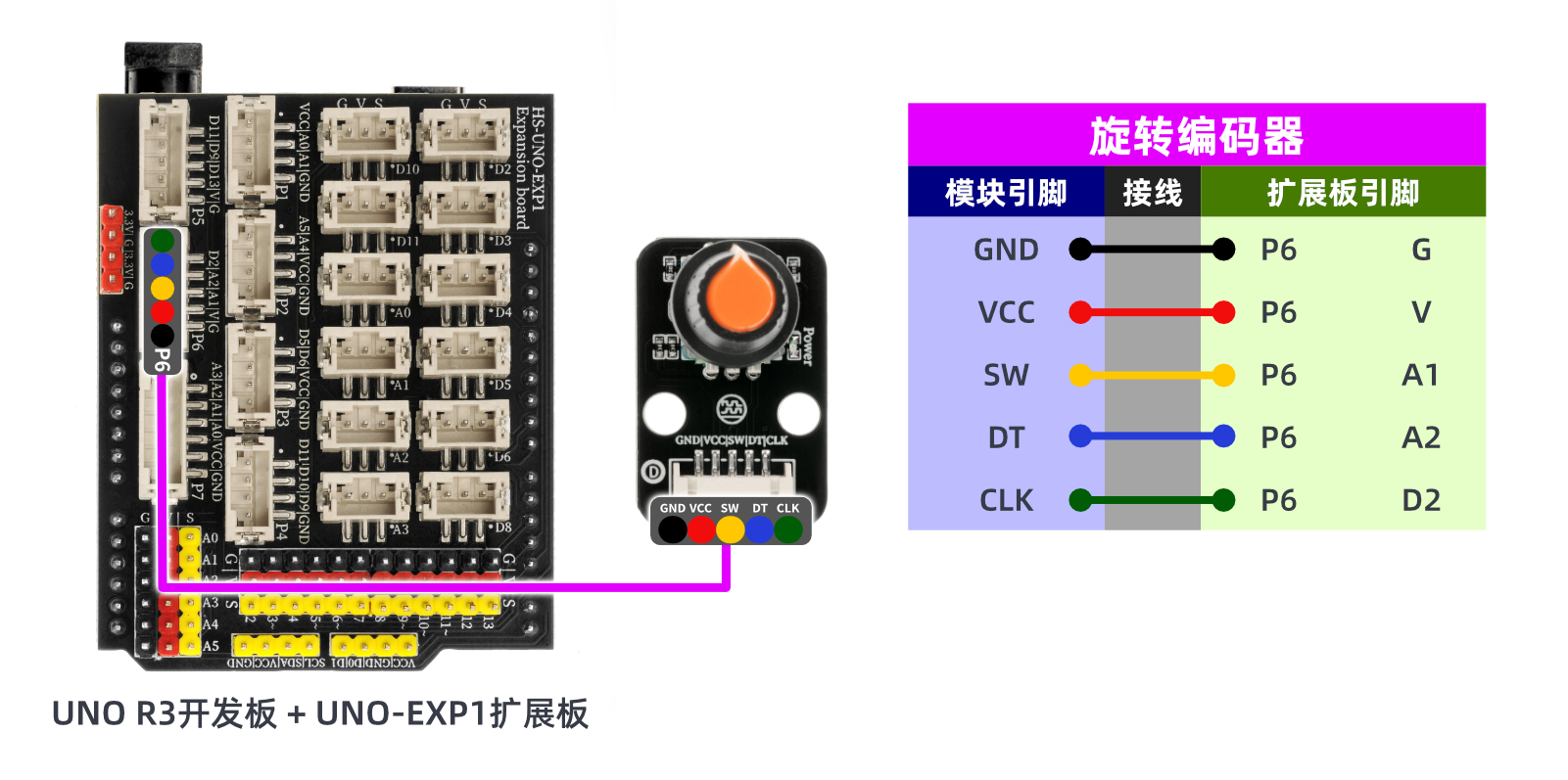
Circuit wiring diagram:
8. Video tutorial
Video tutorial:Click to view
9, test result
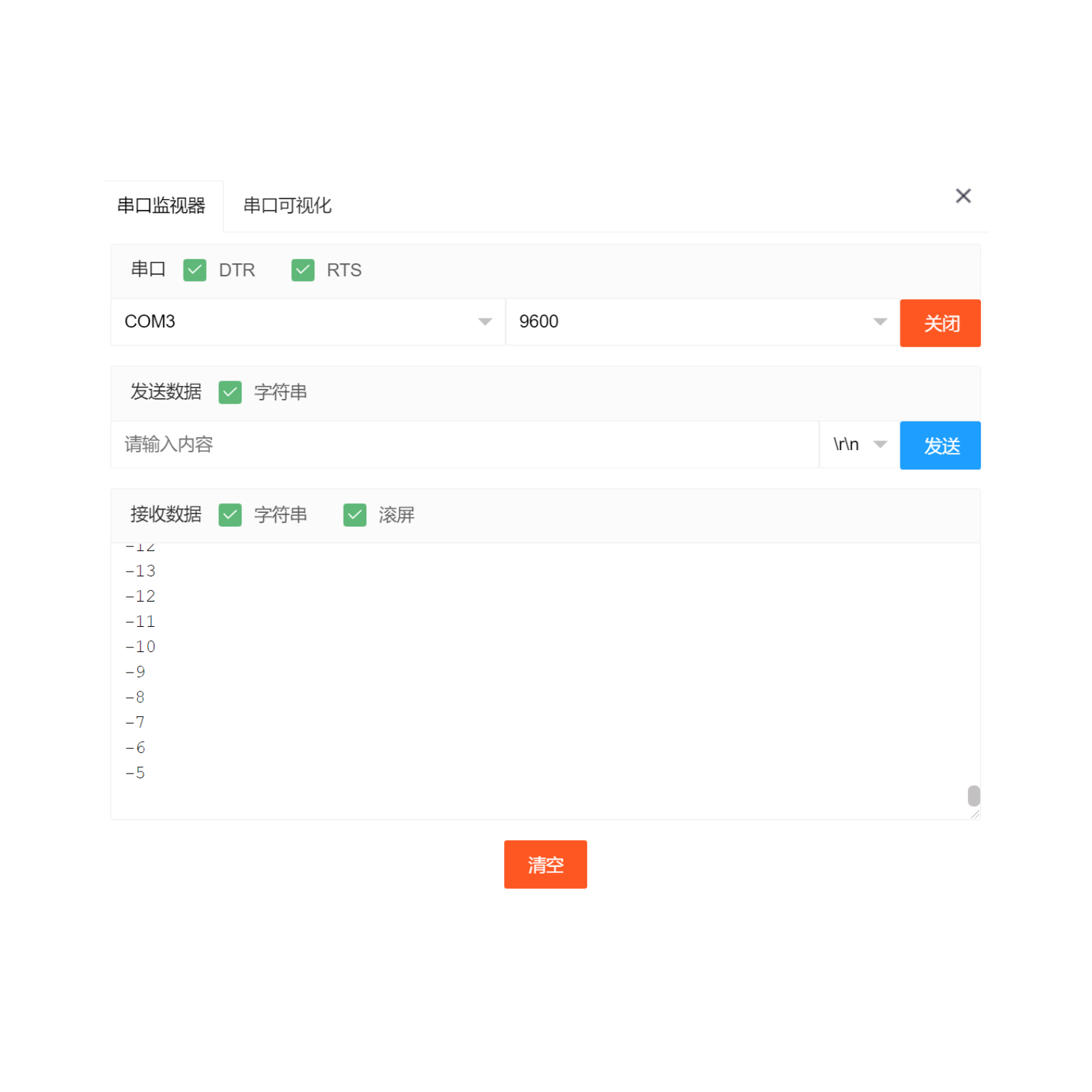
Arduino UNO test results:
Through experimental analysis, the rotary encoder is a unrestricted rotating device, the count increases with clockwise rotation, the count decreases with counterclockwise rotation, and the count resets to zero when the rotary encoder button is pressed.As shown in the figure: Open the Mxily serial port monitor, turn the rotary encoder knob, and the serial port outputs numbers.